
X-ray Source Energies
Technique Overview
When designing an XPS experiment, one of the first things you must think about is which X-ray source you need. Most commonly, monochromated aluminium kα radiation (1486.7 eV) is used as the exciting source however magnesium kα (1253.6) has been used extensively also. While magnesium sources are non-monochromatic, the intrinsic line width of Mg kα is lower than Al kα (0.7 vs 0.85 eV) and hence is the preferred choice of non-monochromatic sources.
Most modern XPS instruments will come with monochromated Al kα as standard, but may also feature a non-monochromated dual anode source (typically Mg/Al) or even a monochromated Ag Lα/Al kα source (such as the Kratos Supra at HarwellXPS).
Applications and Fields
Thin film analysis
Depth Analysis
Buried Interfaces
Monochromatic X-rays are typically preferable since the narrow X-ray line width results in enhanced resolution of spectral features and thus are capable of resolving chemical states with smaller differences in binding energy. The drawback of monochromatic X-rays is of course reduced signal, since you are removing photons from the exciting source, however this is a non-issue with monochromatic Al kα sources, where focusing crystals or focused beams often result in comparable or even high signal than unfocused, non-monochromatic X-rays.
The different energies associated with different X-ray sources result in different kinetic energies and hence different inelastic mean free path lengths. When considering the energies involved with XPS you can generally assume that higher energies result in deeper sampling depths, however this might not hold true for certain orbitals which result in very low kinetic energies.
The universal curve for IMFP is given by λ = 143/E2 + 0.054√ E (Figure 1).(1)
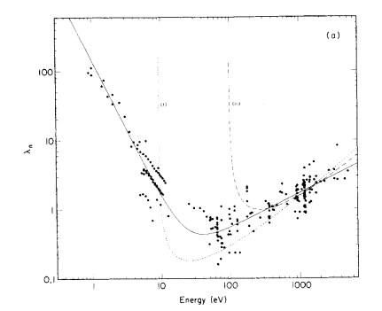
One major advantage of this variation in IMFP can be found when analysing thin films or similar, in which simultaneous equations of intensity attenuation for each source and path length may be used to calculate film thickness.(2,3)
The top end of lab based systems in terms of depth is the liquid Ga source (see the ManchesterXPS team, part of the HarwellXPS national facility) which may reach depths of up to 30-60 nm.
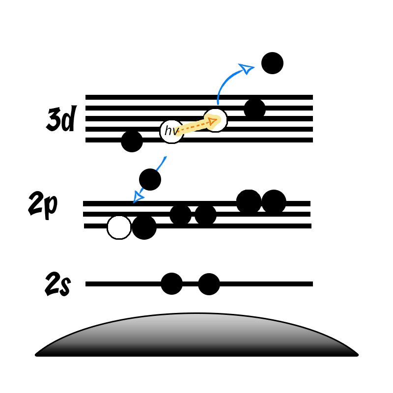
It is not uncommon in XPS to find photoemission peaks of interest overlapping with auger lines from other elements present in the sample (or even the same element in the case of cobalt/Al kα). In this case, analysis using another X-ray energy can help remove this overlap.
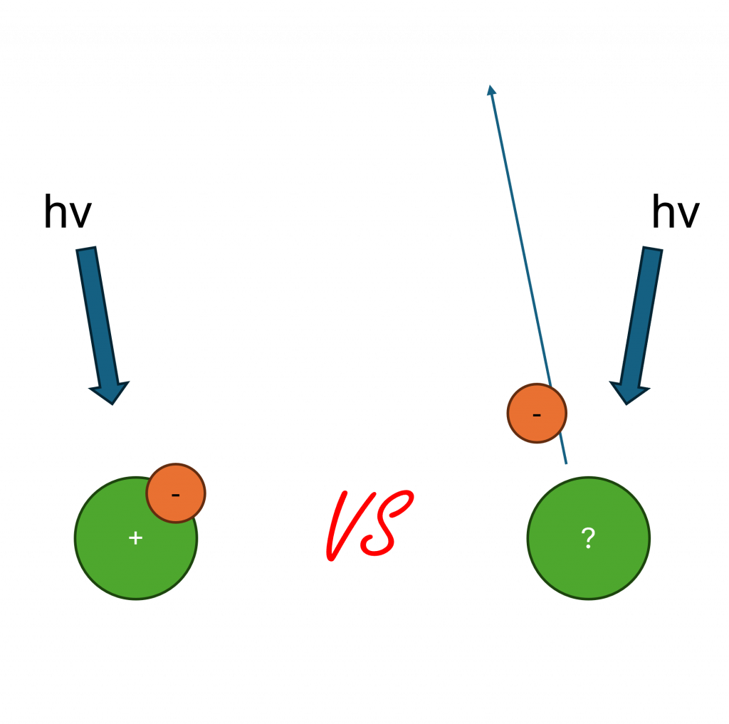
This is a possibility since the kinetic energy of an auger electron is independent of exciting energy. Therefore, when you increase the energy of the incoming radiation, you increase the kinetic energy of the photoelectrons (equation 1) and thus separate auger peak from photoemission.
hv = EK + EB + Φ Equation 1
Commonly used X-ray sources are listed in table 1.
| Anode | Radiation | Energy / eV | Line width / eV |
| Mg | Kα | 1253.6 | 0.7 |
| Al | Kα | 1486.7 | 0.85 |
| Zr | Lα | 2042.4 | 1.6 |
| Ag | Lα | 2984.3 | 2.6 |
| Ti | Kα | 4510.9 | 2.0 |
| Cr | Kα | 5417 | 2.1 |
| Ga | Kα | 9250 |
- Seah, M. P. and W. Dench (1979). “Quantitative electron spectroscopy of surfaces: A standard data base for electron inelastic mean free paths in solids.” Surface and interface analysis 1(1): 2-11. Read it online here.
- Isaacs, M. A., et al. (2017). “Tunable Ag@ SiO 2 core–shell nanocomposites for broad spectrum antibacterial applications.” RSC advances 7(38): 23342-23347. Read it online here.
- Shard, A. G. (2012). “A straightforward method for interpreting XPS data from core–shell nanoparticles.” The Journal of Physical Chemistry C 116(31): 16806-16813. Read it online here.
- XPS Simplified, accessed 14:05 29/05/2020
Advanced Auger Analysis
Learn about the additional information made possible from analysis of Auger-Meitner electrons!

Coster-Kronig Transmissions in XPS
Coster-Kronig transitions cause unequal broadening in spin-orbit doublets
Initial vs Final State Effects
What is the differences between initial, and final state effects?